As the global push for clean and efficient energy systems intensifies, Molten Carbonate Fuel Cells (MCFCs) stand out as a compelling solution for high-efficiency stationary power generation, particularly in industrial and utility-scale applications.
Unlike conventional fuel cells that operate at lower temperatures and require pure hydrogen, MCFCs can run directly on natural gas or biogas, thanks to their high operating temperature and unique carbonate-ion conducting electrolyte.
What Are Molten Carbonate Fuel Cells?
MCFCs are high-temperature electrochemical devices that generate electricity by oxidizing hydrogen or carbon monoxide using oxygen from air. They operate at approximately 650°C (1200°F) and rely on a molten carbonate electrolyte to transport carbonate ions (CO₃²⁻) between electrodes.
Key Components:
- Electrolyte: A molten mixture of lithium and potassium carbonates, retained in a ceramic matrix (usually lithium aluminate) through capillary forces.
- Electrodes:
- Anode: Receives fuel (H₂ or CH₄) and facilitates oxidation.
- Cathode: Draws in oxygen and CO₂ to form carbonate ions.
- Operating Conditions:
- Temperature: ~650°C (1200°F)Pressure: 1–10 barg (15–150 psig)
- Cell Output: ~0.7–1.0 VDC per cell
Ion Movement:
- Carbonate ions (CO₃²⁻) flow from cathode anode through the electrolyte.
- Electrons flow from anode cathode through an external circuit, generating usable electric power.
- Internal Reforming Reaction (for methane)
How Molten Carbonate Fuel Cells Produce Electricity (Made Simple)
Molten Carbonate Fuel Cells (MCFCs) create electricity through chemical reactions between fuel (like hydrogen or natural gas) and air. Here’s a breakdown of what happens inside the cell:
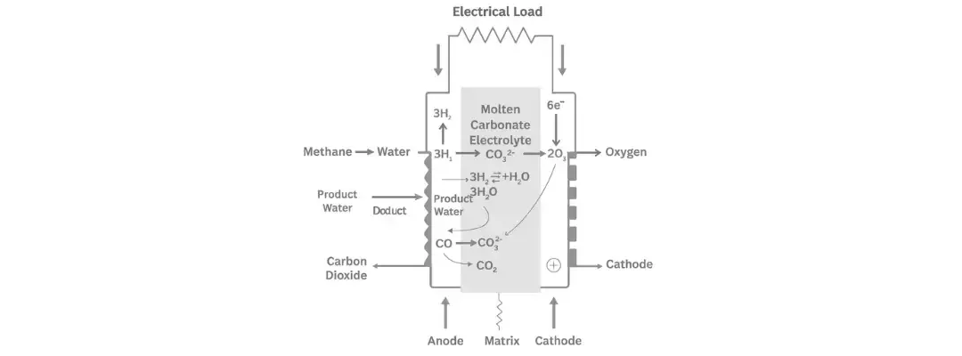
Step 1: Internal Fuel Reforming
If the fuel is a hydrocarbon (like methane), it gets converted into hydrogen and carbon monoxide right inside the fuel cell. This process uses steam and heat:
Methane + Water Hydrogen + Carbon MonoxideCH₄ + H₂O → 3H₂ + CO
This step happens at the anode, using heat and a nickel catalyst.
Step 2: Reactions at the Anode (Fuel Side)
Two main reactions occur here:
- Hydrogen reacts with carbonate ions to make water and carbon dioxide:
3H₂ + 3CO₃²⁻ → 3H₂O + 3CO₂ + 6e⁻ - Carbon monoxide also reacts with carbonate ions to make more carbon dioxide:
CO + CO₃²⁻ → 2CO₂ + 2e⁻
These reactions release electrons (e⁻), which travel through an external wire to power devices.
Step 3: Reaction at the Cathode (Air Side)
At the other end of the cell, oxygen from air and carbon dioxide combine with the returning electrons to make carbonate ions again:
2O₂ + 4CO₂ + 8e⁻ → 4CO₃²⁻
These new carbonate ions go back to the anode to keep the process going.
Overall Reactions (Big Picture)
Depending on the fuel type, the complete reactions look like this:
- If using hydrogen:
2H₂ + O₂ → 2H₂O - If using hydrocarbons (which make carbon monoxide):
CO + ½O₂ → CO₂
Key Advantages of MCFC Technology
MCFCs offer several compelling benefits, especially for stationary power applications:
| Advantage | Description |
| Internal Reforming | Converts light hydrocarbons like methane inside the fuel cell, reducing cost and complexity |
| Cogeneration Ready | High-grade waste heat can be used in combined heat and power (CHP) systems for overall efficiency up to 85% |
| No Precious Metals Required | Operates efficiently with nickel-based catalysts instead of platinum, lowering material costs |
| High Power Efficiency | Electrical conversion efficiency of up to 60% |
| Fuel Flexibility | Operates on hydrogen, natural gas, biogas, or other light hydrocarbons |
| Robust for Industrial Use | Ideal for continuous, long-duration power demands in heavy-duty environments |
Technical Challenges & Limitations
Despite their strengths, MCFCs also present some engineering hurdles:
Material Challenges
- High-Temperature Corrosion: Nickel oxide from the cathode may dissolve into the electrolyte, degrading performance and shortening lifespan.
- Dimensional Instability: Prolonged heat exposure can deform electrode structures, increasing electrical resistance and reducing active surface area.
Chemical Sensitivity
- Sulfur Intolerance: Anode performance degrades significantly when exposed to 1–5 ppm of sulfur compounds (like H₂S or COS).
- Liquid Electrolyte Handling: Introduces risks such as electrolyte leakage, seal degradation, and complex maintenance.
Operational Considerations
- Slow Startup: Not ideal for applications requiring rapid cycling or immediate power availability.
- System Complexity: Requires precise thermal management and gas balance control.
Ideal Applications for MCFCs
Given their fuel flexibility, high efficiency, and waste heat recovery capabilities, MCFCs are best suited for:
- Utility-Scale Power Plants
- Industrial Cogeneration (CHP)
- Waste-to-Energy Facilities
- Grid Support & Distributed Generation
Their ability to use natural gas or biogas makes them especially attractive in areas where hydrogen infrastructure is still developing.
At-a-Glance Summary: MCFC Characteristics
| Feature | Molten Carbonate Fuel Cell (MCFC) |
| Electrolyte | Molten Li/K Carbonate in ceramic matrix |
| Operating Temp | ~650°C (1200°F) |
| Ion Conducted | Carbonate ion (CO₃²⁻) |
| Fuel Options | Hydrogen, methane, biogas |
| Startup Time | Slow |
| Efficiency | 60% (electrical), 85% (with cogeneration) |
| Catalyst | Nickel (non-noble metal) |
| Key Advantages | Fuel flexibility, internal reforming, high efficiency |
| Key Drawbacks | Corrosion, sulfur sensitivity, thermal management |
| Ideal Use Cases | Stationary, industrial-scale power and CHP systems |